Versions #
| Product Name | Type | Generation | Product Number |
|---|---|---|---|
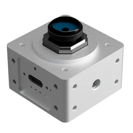
| Camera | USB-C Single IMU 3MP | 01 | CAM-U01X3M-S |
| Camera | USB-C Single IMU 3MP TPU | 01 | CAM-U01X3M-S-TP |
| Camera | USB-C Single IMU 3MP Global Shutter | 01 | CAM-U01X3M-S-G |
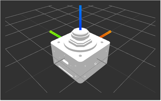
3D Coordinate System
#
Technical Specifications #
| Feature Category | Feature Subcategory | Specification |
|---|---|---|
| Form Factor | Dimensions (W x H x D) | 40mm x 40mm x 30mm |
| Weight | 89 grams | |
| Processor Unit | Application Processor | Dual Cortex-A7 up to 800 MHz |
| Real-Time Processor | Cortex-M4 MPU up to 200 MHz | |
| TPU AI Accelerator | 4 Trillion Operations Per Second | |
| Memory | On Chip (SoC) | 512 MB RAM |
| On Chip EEPROM (SoC) | 512 Bytes x 8 | |
| On SOM | 64 GByte SD Flash | |
| Sensors | Image Sensor | 1/2.7″ OmniVision OV2710 |
| Max Resolution | 1920(H)x1080(V) pixels | |
| Lens | 2.1mm (L210) / 1.8mm (L180) | |
| Frame Rate | 640×480 VGA @120fps, 1280×720 HD @60fps, 1920×1080 FHD @30fps | |
| IMU Sensor | 6-Axis Automotive-Proven IMU | |
| IMU Range & Sensitivity | Accelerometer: 0.06 mg/LSB, Gyroscope: 0.004 dps/LSB | |
| Connectivity | High-Speed Connectivity | 1x Virtual Ethernet USB Type C @ 60 MBps |
| Other I/O | 1x User Switch, 3x User LEDs | |
| Software | Yocto BSP | Available for batch purchases |
| Linux Kernel | Linux 5.10 | |
| Operating System | Debian 11 | |
| Communication middleware | Apache Cyclone DDS | |
| Robotic Operating Systems | ROS Noetic Ninjemys, ROS 2 Humble Hawksbill | |
| Power and Thermal | Power Consumption | USB Type C PD (15 W max) |
| Voltage | PD 5.0v | |
| Max Current | 3000mA | |
| Temperature Range | Commercial: 0°C to 85°C, Industrial: -40°C to +85°C |
TPU #
A TPU, or Tensor Processing Unit, is a type of AI accelerator specifically designed by Google to accelerate machine learning tasks. TPUs are application-specific integrated circuits (ASICs) that have been optimized for the efficient execution of tensor operations, which are fundamental to deep learning and other machine learning algorithms.
The primary goal of a TPU is to enhance the performance and energy efficiency of machine learning workloads, allowing AI models to be trained and executed more quickly and with lower power consumption than traditional CPU or GPU-based hardware. This is achieved through a combination of specialized hardware components and optimizations tailored to the unique requirements of machine learning tasks.
Enable / Disable TPU acceleration #
In order to enable the tpu chip do
./opt/olive/script/enable_tpu.shand to disable the tpu do
./opt/olive/script/disable_tpu.shto verify the TPU is enabled you can do
lsusbThe result will be:
Bus 001 Device 004: ID 1a6e:089a Global Unichip Corp.
Bus 001 Device 003: ID 32e4:9230 HD USB Camera HD USB Camera
Bus 001 Device 002: ID 1a40:0101 Terminus Technology Inc. Hub
Bus 001 Device 001: ID 1d6b:0002 Linux Foundation 2.0 root hub
Bus 002 Device 001: ID 1d6b:0001 Linux Foundation 1.1 root hub
Which the “Global Unichip Corp” is the TPU chip.
TPU Apps #
All the python3 based TPU examples are located in /home/olive/apps. To run an object detection example using TPU after enabling the tpu in the previus step run
python3 /home/olive/apps/packages/src/app_tpu_python/tpu_python/app_node.pyNote that you have to change the topic name of the app subscriber to your current device topic name in oder to subscribe to the image. In order to to this you have to edit the app_node.py
After running this example the camera will detect objects based on Coral object detection example.

General pipeline diagram

For more information about Google® coral please visit:
For other python example source projects please visit:
https://github.com/olive-robotics/olv_camera_tpu_playground_py
General Setup #
Follow the Quick Start for Olive Robotics robot modules to connect the device and start using it.
Quick Setup #
Quick start guide for the olive® Camera module:
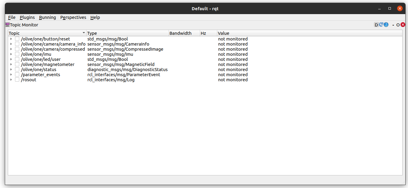
- Check if the data is alreaddy published to your system using:
ros2 topic listyou should be able to see all the topics published from the module. For exampe for IMU module you will see:/olive/imu/id001/image/camera_info/olive/imu/id001/image/compressed/olive/imu/id001/imu/olive/imu/id001/magnetometer/olive/imu/id001/status/parameter_events/rosout
The number id001 is your device’s default namespace.
- Visualize the data using:
- Embedded Web Interface
- rqt (https://docs.ros.org/en/humble/Tutorials/Beginner-CLI-Tools/Introducing-Turtlesim/Introducing-Turtlesim.html#install-rqt)
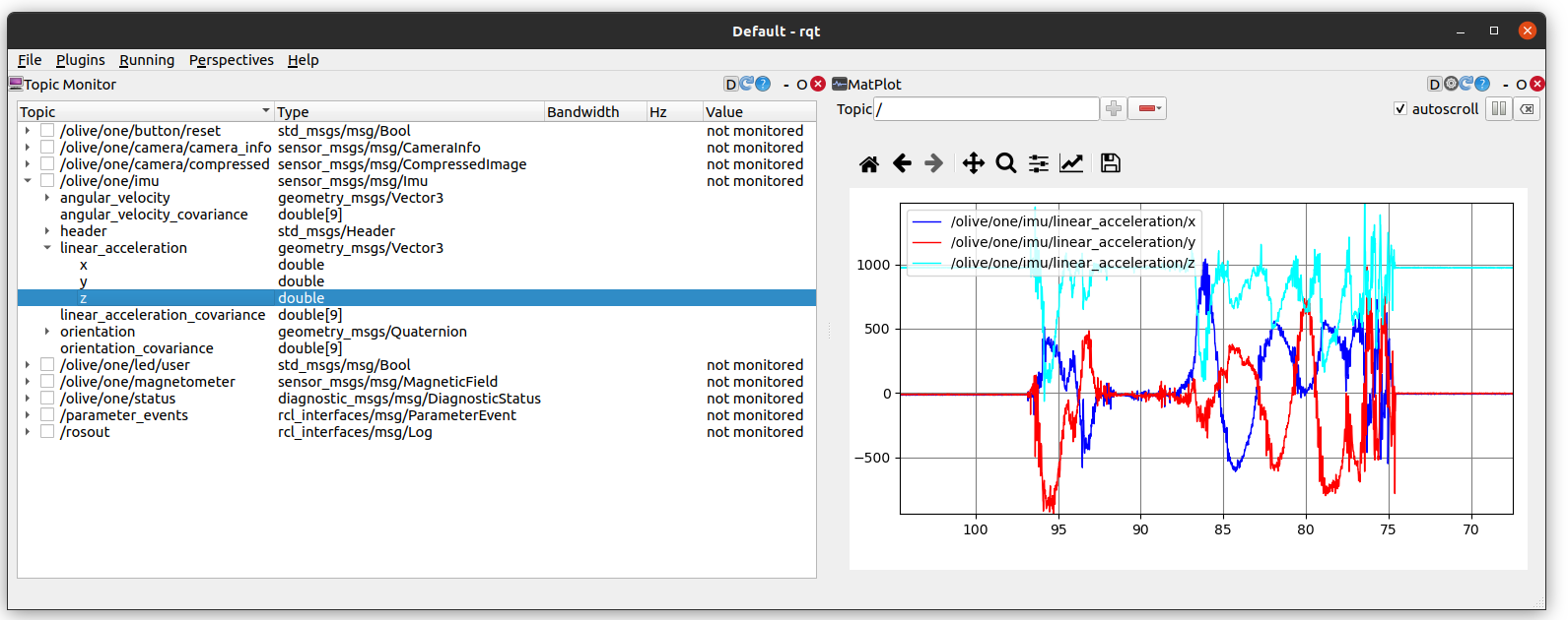
- Visualize the topics:
- Plot the data from the IMU messages:
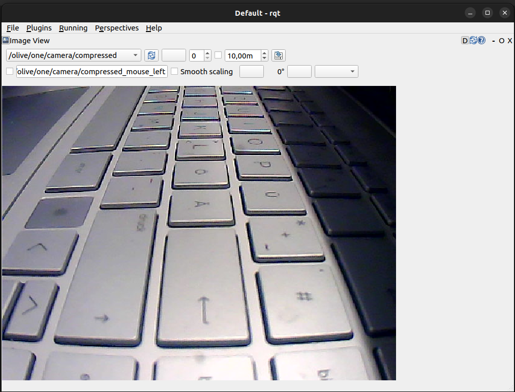
- Visualize the Image:
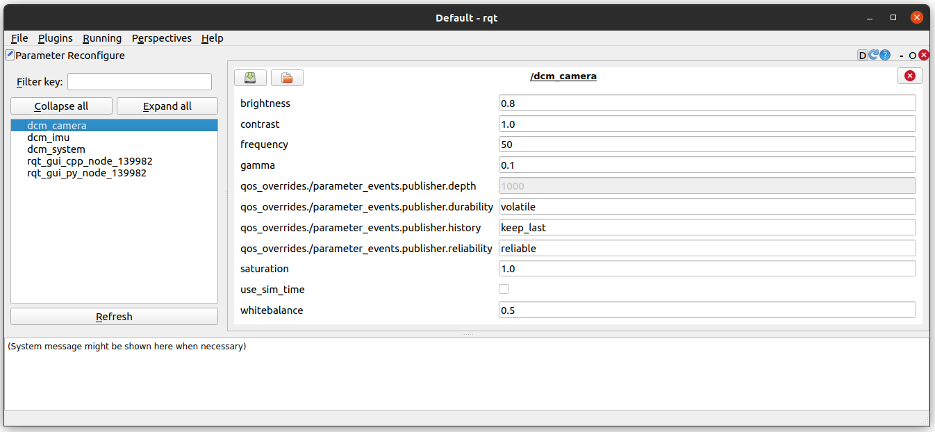
- Change the parameters of the DCM:
- Visualize the topics:
- rviz2 (https://github.com/ros2/rviz).
- Visualize the IMU data in Rviz2
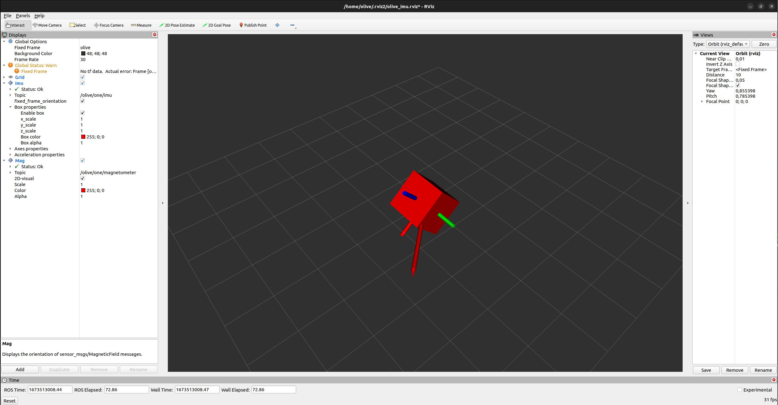
- Visualize the IMU data in Rviz2
- Visualize the data and change the parameters like IP, Topic Name, etc using the embedded web interface.
ROS Topics and Services #
| Topic Name | Message Type | Type | Description |
|---|---|---|---|
| …/image/camera_info | sensor_msgs/CameraInfo | Publisher | Camera image information |
| …/image/compressed | sensor_msgs/CompressedImage | Publisher | Camera image |
| …/imu | sensor_msgs/Imu | Publisher | Messured acc/gyro/quaternion |
| …/magneticfield | sensor_msgs/MagneticField | Publisher | Messured Magnetic field. |
| …/status | diagnostic_msgs/DiagnosticStatus | Publisher | Device status. |
Advanced Settings #
The device allows certain parameters to be changed at runtime. To get an overview of all changeable parameters use ros2 param list. To change a parameter use ros2 param set /dcm_camera <parameter> <new_value>
Camera #
| Parameter | Type | Range Min | Range Max | Default | Description |
|---|---|---|---|---|---|
| frequency | int | 0 | 120 | 30 | Camera publish rate |
| brightness | double | 0.0 | 1.0 | 0.5 | Camera brightness parameter |
| contrast | double | 0.0 | 1.0 | 0.5 | Camera contrast parameter |
| saturation | double | 0.0 | 1.0 | 0.5 | Camera saturation parameter |
| gamma | double | 0.0 | 1.0 | 0.5 | Camera gamma parameter |
| whitebalance | double | 0.0 | 1.0 | 0.5 | Camera whitebalance parameter |
| resolution | string | “320×240” | “1920×1080” | “640×480” | Camera image resolution |
IMU #
| Parameter | Type | Range Min | Range Max | Default | Description |
|---|---|---|---|---|---|
| filter_frequency | int | 0 | 1200 | 100 | IMU filter frequency |
| filter_gain | int | 0 | 1 | 0.2 | IMU filter gain |
| frequency_imu | int | 0 | 1200 | 100 | IMU publish rate |
| frequency_mag | int | 0 | 100 | 100 | Magnetometer publish rate |
System #
| Parameter | Type | Range Min | Range Max | Default | Description |
|---|---|---|---|---|---|
| frequency | int | 0 | 10 | 10 | System status publish rate |
Advanced setup #
Camera Calibration #
- Install Camera Calibration Parser, Camera Info Manager and Launch Testing Ament Cmake
sudo apt install ros-humble-camera-calibration-parsers
sudo apt install ros-humble-camera-info-manager
sudo apt install ros-humble-launch-testing-ament-cmake- The image_pipeline need to be built from source in your workspace with:
git clone – b humble git@github.com:ros-perception/image_pipeline.git- A large checkerboard with known dimensions. This tutorial uses a 7×9 checkerboard with 20mm squares. Calibration uses the interior vertex points of the checkerboard, so an “8×10” board uses the interior vertex parameter “7×9” as in the example below. The checkerboard with set dimensions can be downloaded from here.
https://calib.io/pages/camera-calibration-pattern-generator
- A well-lit area clear of obstructions and other check board patterns
- A monocular camera publishing images over ROS
ros2 run camera_calibration cameracalibrator --size 7x9 --square 0.02 --ros-args -r image:=/my_camera/image_raw -p camera:=/my_cameraExplanation of the required parameters:
Camera Name:

-c, --camera_name
        name of the camera to appear in the calibration file

Chessboard Options:

You must specify one or more chessboards as pairs of --size and--square options.

  -p PATTERN, --pattern=PATTERN
                    calibration pattern to detect - 'chessboard','circles', 'acircles','charuco'
  -s SIZE, --size=SIZE
                    chessboard size as NxM, counting interior corners (e.g. a standard chessboard is 7x7)
  -q SQUARE, --square=SQUARE
                    chessboard square size in meters

ROS Communication Options:

 --approximate=APPROXIMATE
                    allow specified slop (in seconds) when pairing images from unsynchronized stereo cameras
 --no-service-check
                    disable check for set_camera_info services at startup

Calibration Optimizer Options:

 --fix-principal-point
                    fix the principal point at the image center
 --fix-aspect-ratio
                    enforce focal lengths (fx, fy) are equal
 --zero-tangent-dist
                    set tangential distortion coefficients (p1, p2) to
                    zero
 -k NUM_COEFFS, --k-coefficients=NUM_COEFFS
                    number of radial distortion coefficients to use (up to
                    6, default 2)
 --disable_calib_cb_fast_check
                    uses the CALIB_CB_FAST_CHECK flag for findChessboardCorners
This will open a calibration window which highlight the checkerboard.

As the checkerboard is moved around the 4 bars on the calibration sidebar increases in length. When all then the 4 bars are green and enough data is available for calibration the CALIBRATE button will light up. Click it to see the results. It takes around the minute for calibration to take place.

After the calibration is completed the save and commit buttons light up. And you can also see the result in terminal.
Press the save button to see the result. Data is saved to “/tmp/calibrationdata.tar.gz”

default factory calibrated parameters for 320×240 are as follows:
image_width: 320
image_height: 240
camera_name: narrow_stereo
camera_matrix:
  rows: 3
  cols: 3
  data: [353.88557,   0.     , 160.14916,
        0.     , 353.7126 ,    117.27734,
        0.     ,   0.     ,   1.     ]
distortion_model: plumb_bob
distortion_coefficients:
  rows: 1
  cols: 5
  data: [-0.428635, 0.167437, 0.001243, 0.004107, 0.000000]
rectification_matrix:
  rows: 3
  cols: 3
  data: [1., 0., 0.,
         0., 1., 0.,
         0., 0., 1.]
projection_matrix:
  rows: 3
  cols: 4
  data: [319.03568,   0.     , 161.28226,   0.    ,
        0.     , 334.55365, 116.9051 ,   0.     ,
        0.     ,   0.     ,   1.     ,   0.     ]
place the ost.yaml in the current folder of the camera:
/opt/olive/config/current/cameraNow restart the camera and it should use your new calibration parameters for camera_info topic.
Downloads #
Supported Camera Lenses #
| Lens | Focal Length (mm) | Max Aperture | Sensor Size | Features | Predicted FOV (°) |
|---|---|---|---|---|---|
| 2.8-12mm 1:1.4 IR | 2.8-12 | f/1.4 | 1/2.7″ | Manual focus, zoom | ~28° – ~90° |
| Far-view | 2.6 | f/2.6 | 1/4″ | N/A | ~55° |
| Low-distortion Lens | 3.6 | N/A | 1/2.7″ | N/A | ~60° |
| Fisheye Lens | 10 (estimated) | f/2.8 (estimated) | 1/2.3″ (estimated) | N/A | 187° |
Mechanical Details #


